This iPi is the new Linux iMac

If you search for the "Buy now" button, I have to disappoint you. But please keep on reading.
Let me present you my last finished home project - the iPi. It's a 24 inch Acer Display coupled with a RaspberryPi 3. Both bundled together into what I call the iPi as the RaspberryPi has been built into the screens body, just like the favorite Apple iMac.
Let me show it to you in action!
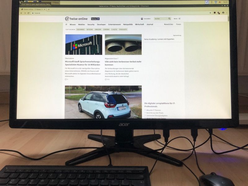
There is only one power cable for the display, one power cable for the RPi and a USB mouse and keyboard. WiFi is built-in to the RPi, so I can use my iPi to surf the web!
Why I built it
Well, this is easy to answer. I saw an interesting Youtube video from a tech youtuber who used an old iMac and put a new M1 Mac mini into the body and so he basically built the worlds first (unofficial) M1 iMac.
Initially I wanted to build that on my own too but I had to spend too much money for this home project, so I thought about what else I could do.
This is where I stumbled over an old display that still worked perfectly and I had a spare RPi 3 laying around. So, why not coupling these into my very own Linux iMac - the iPi?!
So the project started 3 weeks ago. My initial plan only was to somehow put the RPi onto the display and glue them together but then I thought, putting the RPi into the display body and exposing the necessary ports from the RPi to the outside of the screens body would be a bit more challenging and much more professional. Plus, I haven't seen an RPi built into a display yet on any other website or on Youtube. So let's start the journey.
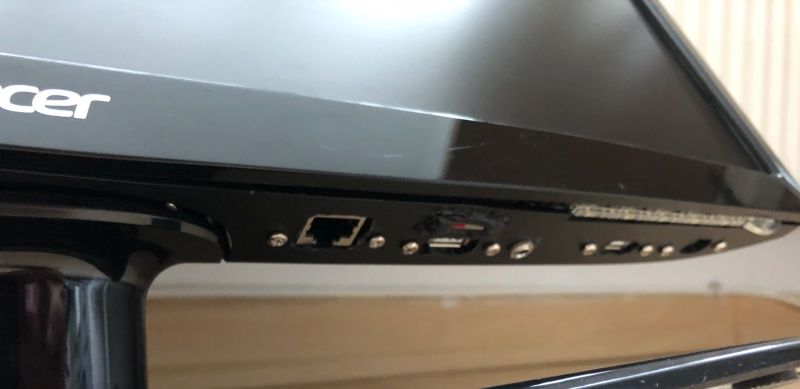
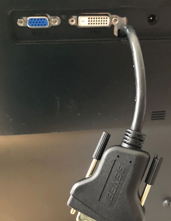
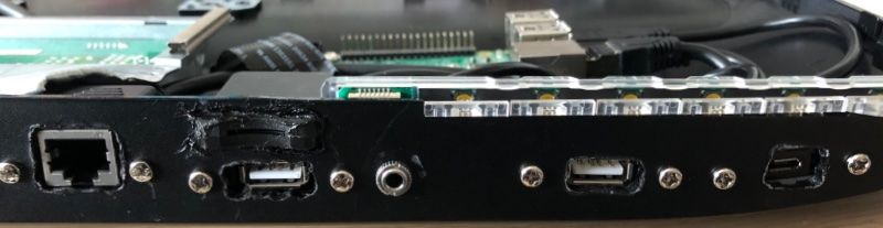
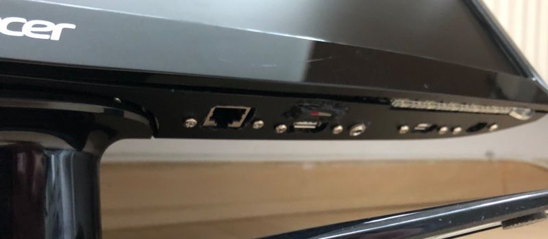
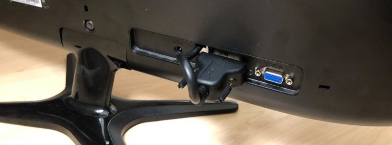
Now 3 weeks later I have a fully working 24" screen which still can work standalone or as the display for the built-in RPi using a DVI to HDMI adapter cable. I also exposed the microSD card slot, the micro-USB power port, 2 USB ports as well as the audio and ethernet port. And due to the plastic back of the display, WiFi and Bluetooth are working fine without additional antennas.
I tried to have as much pictures as possible and and less text as possible, so everything fits into one blog post. Please follow along for teardown and manufacturing of the iPi.
Teardown our iPi display
First, unscrew the stand and the smaller screw that hides underneath it on the displays back. I have used my iFixit ProTech Toolkit for all the work. I have not been sponsored but I can really recommend this toolkit for these kind of work. It contains all the necessary tools and they are great to work with, durable and reliable.
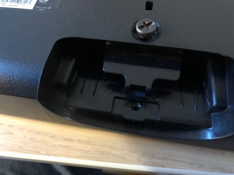
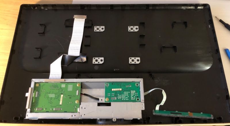
First unscrew the stand and the screw that hides underneath. Then use the spudger or steel blade to separate the displays front cover. I've turned around the front cover on the short edge, so you can see where it is hold down to the main chassis. You need just a little strength to separate them. Nothing broke when I did this the first time, so don't be too careful with it.
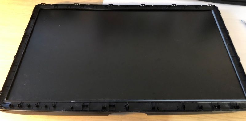
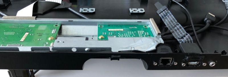
Next, separate the LCD panel from the main chassis and the controller and power board. For that only slightly lift the panel and remove the smaller power cable from the PCB board and remove the larger cable from the top of the LCD panel. You can press together both sides of the connector and then pull it downwards. Then put the panel aside for now.
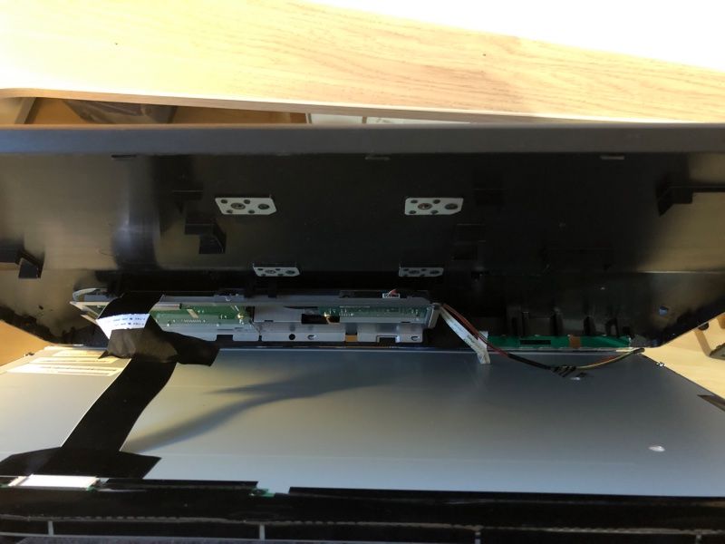
You now have the main chassis and the controller and power board. I then checked where to put the RPi and the extension cables. I also though about which cables I may need for the RPi and how much flexibility I want to have.
In the end my goal was to be able to have at least one Keyboard and Mouse connected as well as speakers and maybe a network cable. I also wanted to be able to replace the microSD card to put in a new OS or replace a potentially defective one.
Also I wanted to have the display being useable standalone, so I needed a way to connect the RPi to it "externally" but somehow internal.
Let's get the cables first.
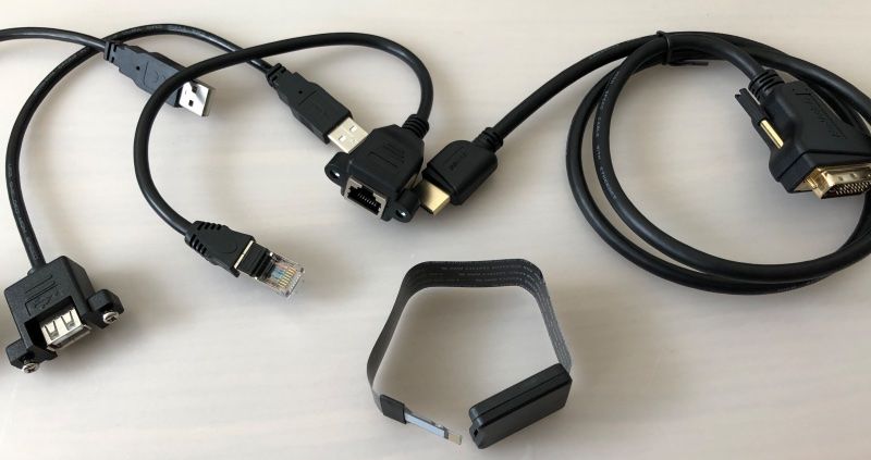
The cables I ordered are the following:
- https://www.amazon.de/gp/product/B078567K85/ref=ppx_yo_dt_b_asin_title_o01_s00?ie=UTF8&psc=1
- https://www.amazon.de/gp/product/B0754MNQPN/ref=ppx_yo_dt_b_asin_title_o02_s00?ie=UTF8&psc=1
- https://www.amazon.de/gp/product/B0793LL5YH/ref=ppx_yo_dt_b_asin_title_o03_s00?ie=UTF8&psc=1
- https://www.amazon.de/gp/product/B01EF000NM/ref=ppx_yo_dt_b_asin_title_o03_s00?ie=UTF8&psc=1
- https://www.amazon.de/gp/product/B07ZF442QH/ref=ppx_yo_dt_b_asin_title_o03_s00?ie=UTF8&psc=1
- https://www.amazon.de/gp/product/B07ZPP372J/ref=ppx_yo_dt_b_asin_title_o03_s00?ie=UTF8&psc=1
- https://www.amazon.de/gp/product/B01MXONLEG/ref=ppx_yo_dt_b_asin_title_o04_s00?ie=UTF8&psc=1
Then I started to put in the cables step by step. Sadly I didn't have proper tools to cut out the chassis plastics. I had to use a combination of my drilling machine and a soldering iron to get the holes I need. Not very professional but fortunately you don't see the holes anymore when the iPi stays upwards afterwards.
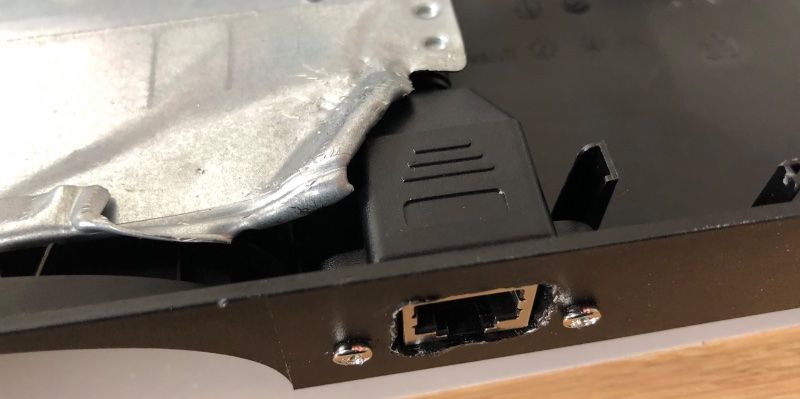
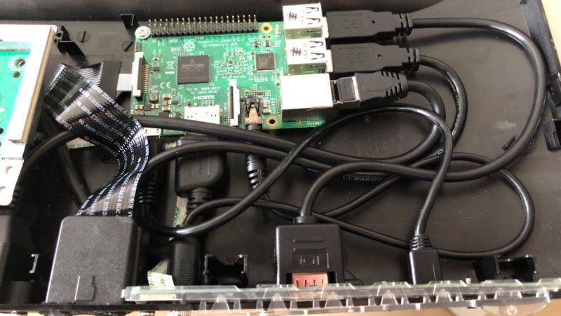
After some drilling and ironing out the plastic, I put in all the cables. I also put in the RPi then, saved it with one screw to the main chassis and connected all cables to it.
This is how the end result looks like. A bit chaotic but it works.
Test our new iPi build
Now it was time to test our new iPi. So I connected the panel back to the controller and power board and put in a working microSD card and the Micro-USB power adapter.
And. It. Worked.
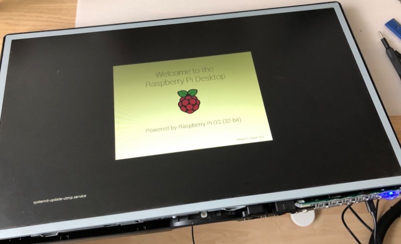
The first boot of my brand new homebrew iPi. Just one power cable for the display and one for the RPi 3 and a bootable microSD card. Et voila!
I then put back the front cover and put back in the screws. My very first iPi was born!
I connected it to my WiFi network and a keybord and mouse. And I was able to properly surf the web. Fantastic!
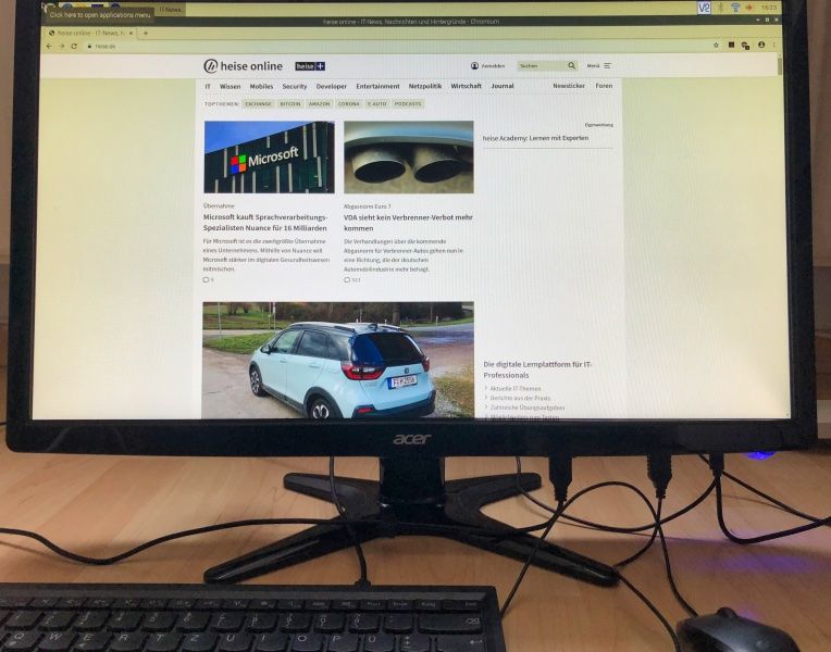
The overall costs for this project where basically the cables I bough on Amazon for some 50-60€ at the time. The RPi 3 costs about 35€ and the display has been standing around for some time now. This is now a perfect device for a reasonably well Home Office PC and can even run Youtube, Netflix and alike in the lunch break.
Conclusion
When I started the project I had no idea how this would end. I am very happy about the result and proud of it. And I mostly recycled parts I already had laying around for some time and brought them to life again together.
Also, if this setup ever gets too slow, I can simply open the screen, replace the RPi 3 with an RPi 4 or newer, close it again and enjoy an upgraded iPi for just a couple of bucks.